Dual Channel GPS Monitor
This board is used to connect two GPS receivers
to a host computer. The GPS Monitor board requires the
eZ80 Networked Motherboard,
with the eZ80 being responsible for choosing the GPS with the
best fix and connecting it to the host system.
Inspired by work done at high lattitues to measure the depth
of glacial ice fields. The problem that occurs occasionally
is the need to operate with receiving antennas located in the
window of an aircraft. At high lattitudes the view of the
sky can be poor from the pole-facing window.
Our soultion is to place 2 recieves in opposite sides of the aircraft
and pick the receiver reporting the best view. This unit also provides
a display that we can use to examine the two receives without the need
to have the main computer active.
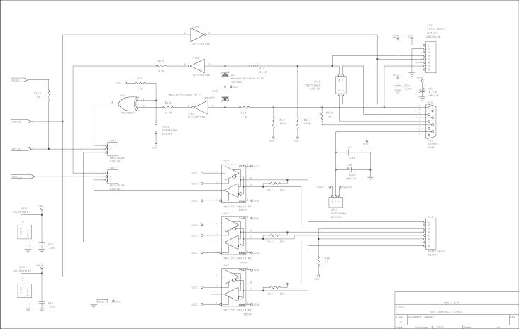
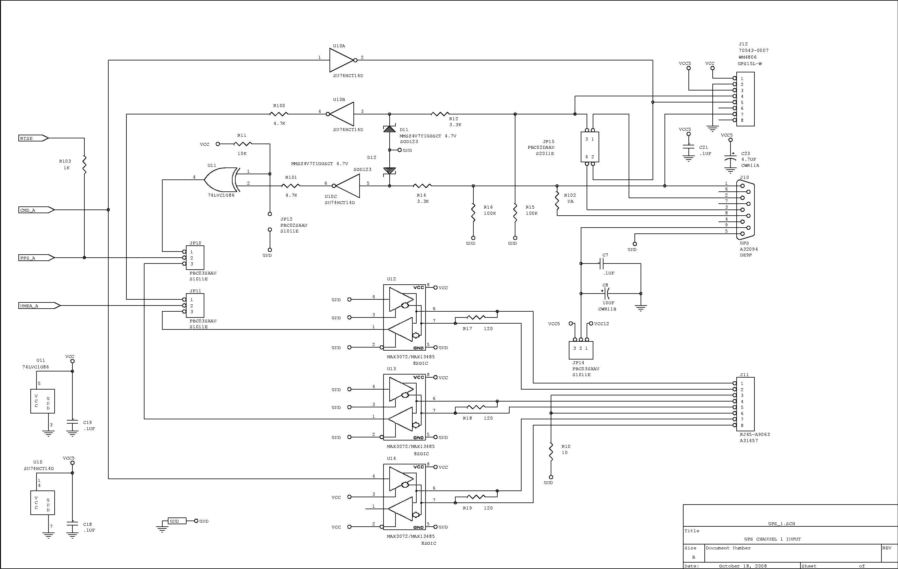
GPS Channel 1 (1/7)
Buffers for connecting one of the GPS receivers.
J10 is a DE9P connector for connecting a GPS receiver
(such as Garmin GPS16/GPS18). The GPS is expected to
provide CMOS/TTL levels (i.e. 3.3V or 5V logic levels).
J12 is an internal header to allow connecting an OEM unit with
a remote antenna (such as a GPS15).
J11 allow connecting to a GPS repeater as used in the labs in Van Allen
Hall (this is a RS485 connection to a roof mounted GPS reciever).

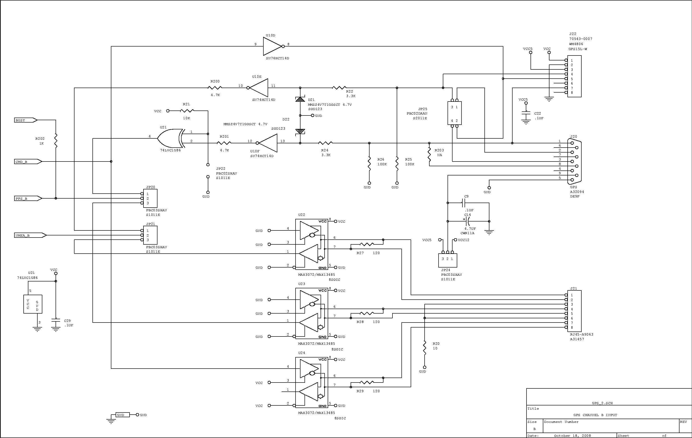
GPS Channel 2 (2/7)
Pretty much identical to the 1st. GPS channel
(jumper comments apply to channel 1).
Jumpers JP20 and JP21 select the source. It should be obvious that
only one of the three GPS sources may be used at any one time.
JP22 is used to control the poalrity of the PPS pulse.
JP25 may be used to swap transmit and receive data, if the
GPS is not wired accordingly.
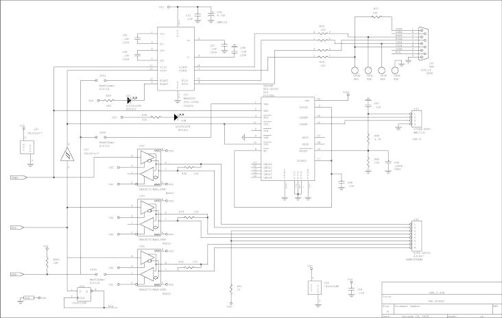
Host Interface (3/7)
Typically the host system is connected to J31 to allow the PPS
signal to be used. The USB port provides a means for a 2nd.
host system to capture the NMEA strings (PPS accuracy for the
USB connection degrades to no better than 1mS accuracy).
There are a set of jumpers that allow connecting the host system
to the command (i.e. Rx Data) line of the GPS receiver. The eZ80
does not look at this line, so it becomes necessary to control which
GPS is selected manually using the front panel switches.
In normal operation, all of these jumpers would be removed
and the eZ80 software would be tailored to command the GPS
into a default setup.
JP31 allows J31(DE9S) to command the GPS receiver(s).
JP35 allows J33(USB) to command the GPS receiver(s).
JP36 allows J33(Remote Host) to command the GPS receiver(s).
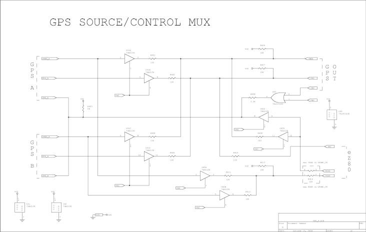
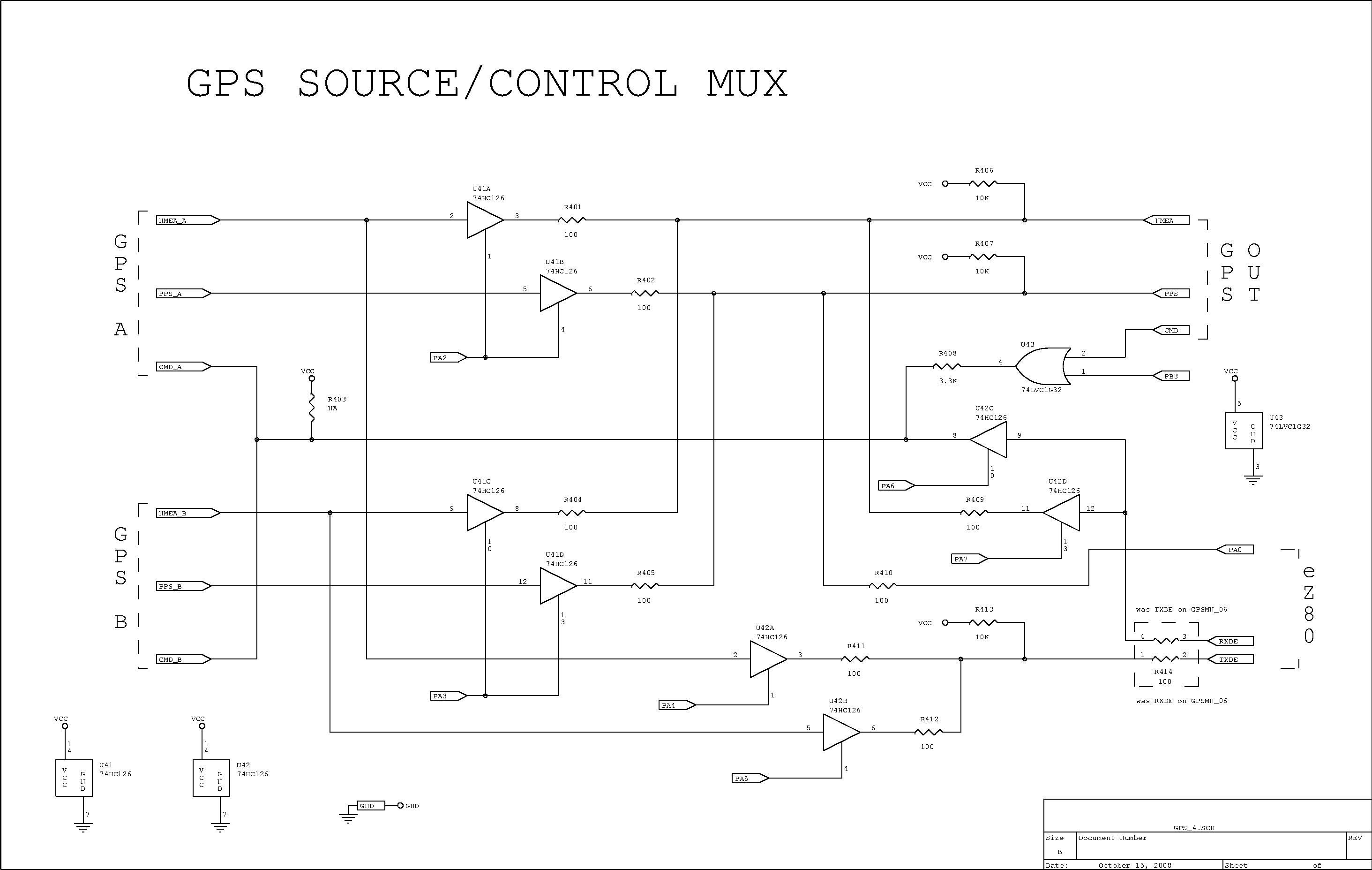
eZ80 Multiplexer (4/7)
This circuitry is used to connect the better GPS unit to the
host system. It is also possible for the eZ80 to simulate
a GPS unit by producing the NMEA strings.
The eZ80 controls the multiplexer through its Port-A and Port-B pins.
R414 is provision for swapping RXDE and TXDE.
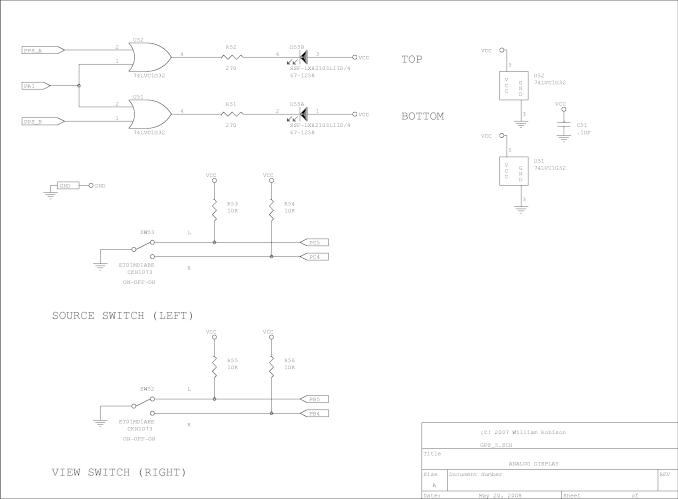
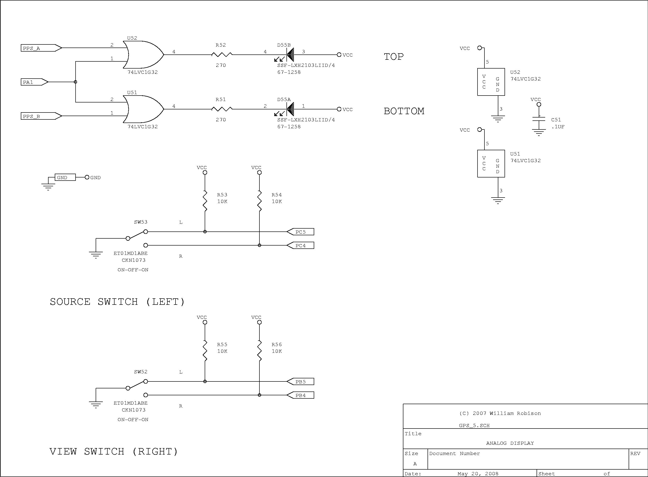
Front Panel indicators/switches(5/7)
The board has 2 LED indicators that connect to the PPS signals
from the 2 recievrs to provide an indication when they are running.
Two center-off toggle switches provide control of the system.

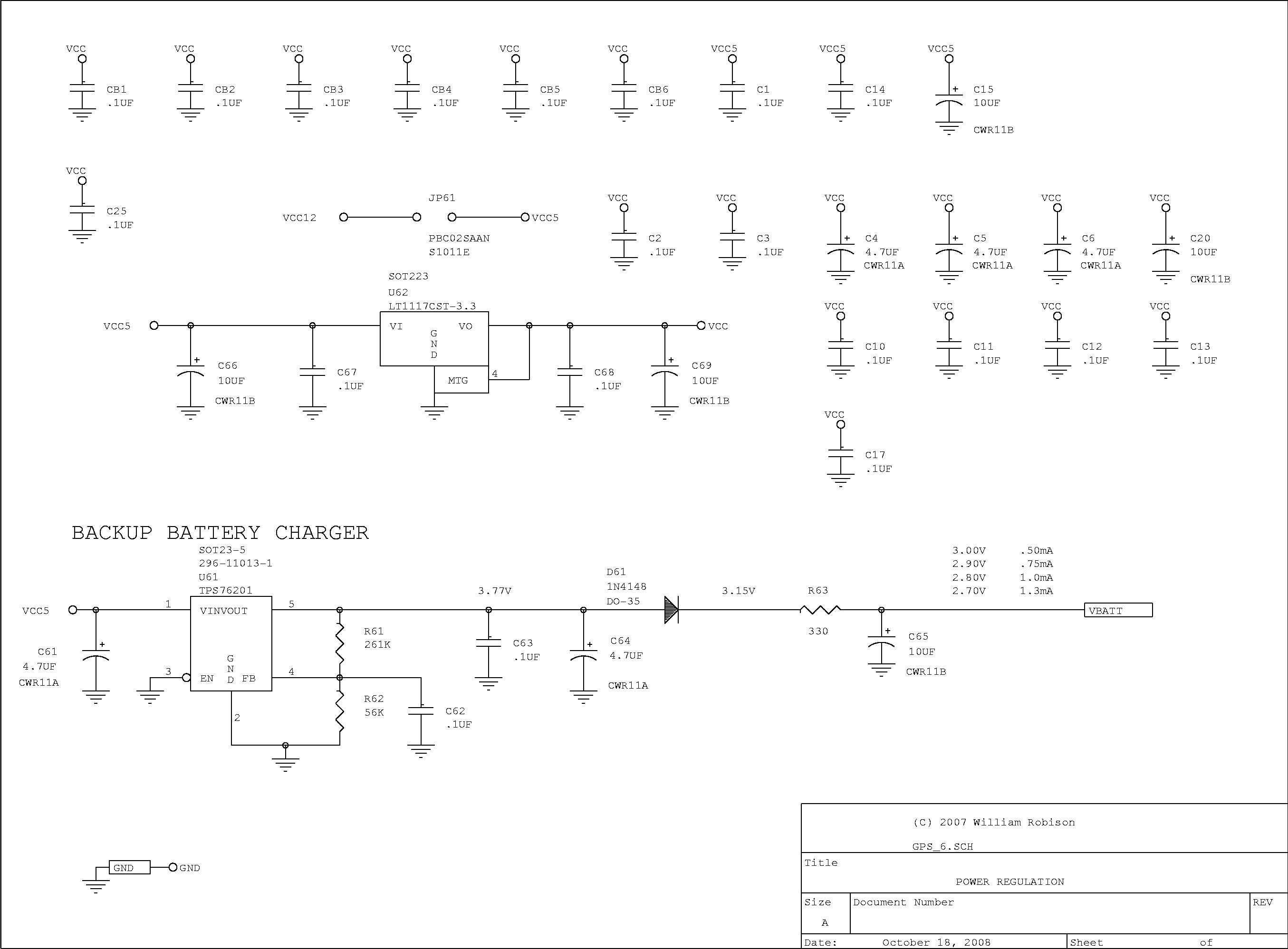
Regulators (6/7)
This block also provides the charger for the backup battery. This is simply
a small adjustable regulator that is trimmed to provide the appropriate
voltage to the backup battery.
Normally, the eZ80 motherboard provides 5V regualtoed power to this
board. If we are running with GPS units that require 5V
(rather than 12V), JP61 is provided to bypass the regulators
to allow 5V to be supplied to the box
(reducing overall power consumption).

Board Interconnect (7/7)
This is the connector schematic from the motherboard, forcing the
pinouts between the boards to match.
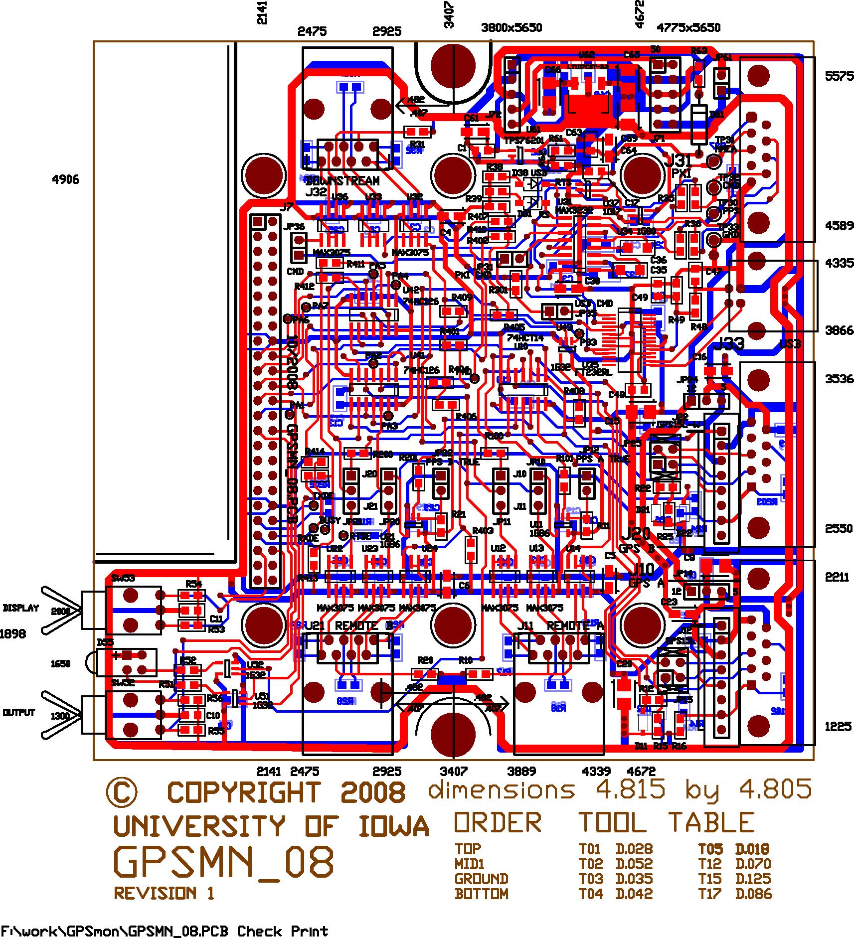
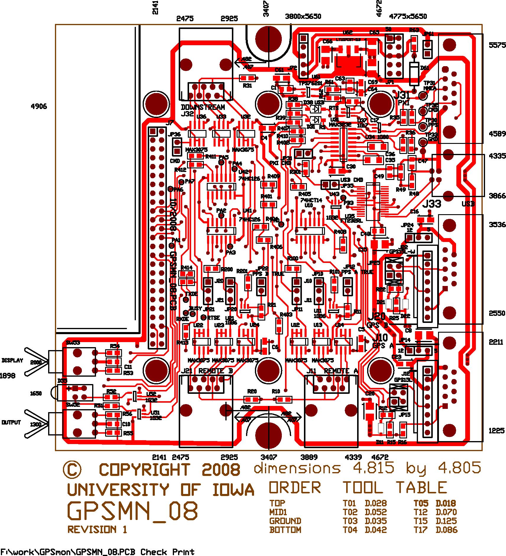
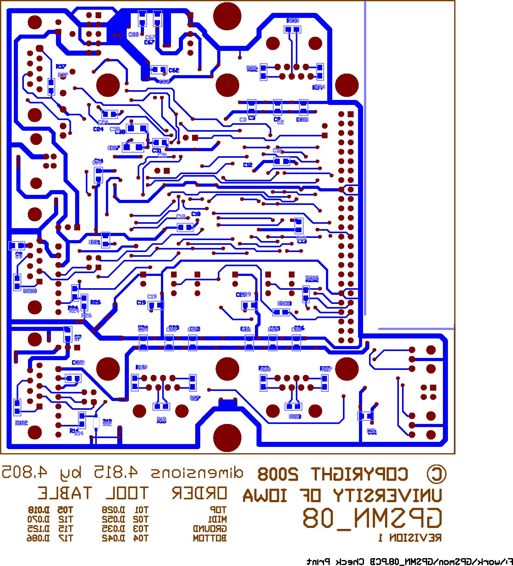
Artwork
These panels have top and bottom copper as well as silkscreen.
This is a 2-layer design. Dimensions for various mounting holes
were used to produce the panels.
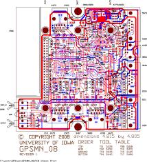
Check Print Postscript
J11, J21, and J32 provide connections to our GPS repeater boards.
To use them requires that the box be modified with an opening to
provide access to the connector (they are not used in the intended
application).
GPS Monitor Daughterboard
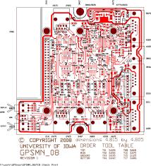
Top Layers Postscript
Probe points next to J31 allow access to the signals going to the
host computer (in the application this is designed for, a NI PXI
chassis).
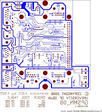
Bottom Layers Postscript
Panels
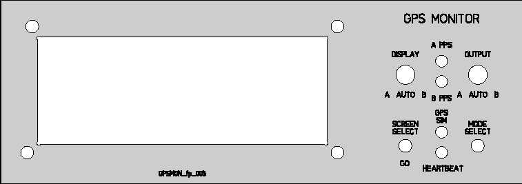
Front Panel PPM
Display toggle
Selects the source of the data displayed on the LCD screen.
Output toggle
Selects the source of the data delivered to the USB/PPS and PXI/PPS
connectors.
Screen Select button
Selects the NMEA data that is displayed on the LCD.
Mode Select button
GPS Programming modes.
A PPS LED
Pulse-per-second signal from GPS receiver A
B PPS LED
Pulse-per-second signal from GPS receiver B
GPS SIM LED
Indicates the eZ80 is simulating NMEA data.
HEARTBEAT LED
Indicates the eZ80 is running
Mechanical Details
The cutout is dimensioned for a Matrix Orbital MOS-AL-162 display.
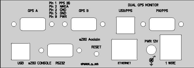
Rear Panel PPM
GPS A DE9
GPS Receiver Connector, pinout noted on panel.
GPS B DE9
GPS Receiver Connector, pinout noted on panel.
USP/PPS USB "B" connector
GPS Output to host system
NOTE PPS accuracy is limited to no better than 1mS
when using the USB connector.
PXI/PPS DE9
GPS Output to host system
USB USB "B" connector
Debugging terminal
RS232 DE9
Debugging Terminal
Reset button
System Reset
Etherent RJ45
NMEA traffic is delivered using a UDP protocol.
Power 5.5 x 2.5
7.5 to 12V power supply.
1 Wire RJ45
Not used in the GPM Monitor Application
Partlists
GPS Monitor
Enclosure Hammond 1598BSGY or 1598BBK
Interboard Standoff are 0.625" Aluminum Hex Spacers
The enclosure has 6 mounting boss's that may be drilled
0.125" to allow the board stack to be attached using 4-40
screws through the Al spacer.