![]()
| Software Version |
Notes & Comments |
|---|---|
|
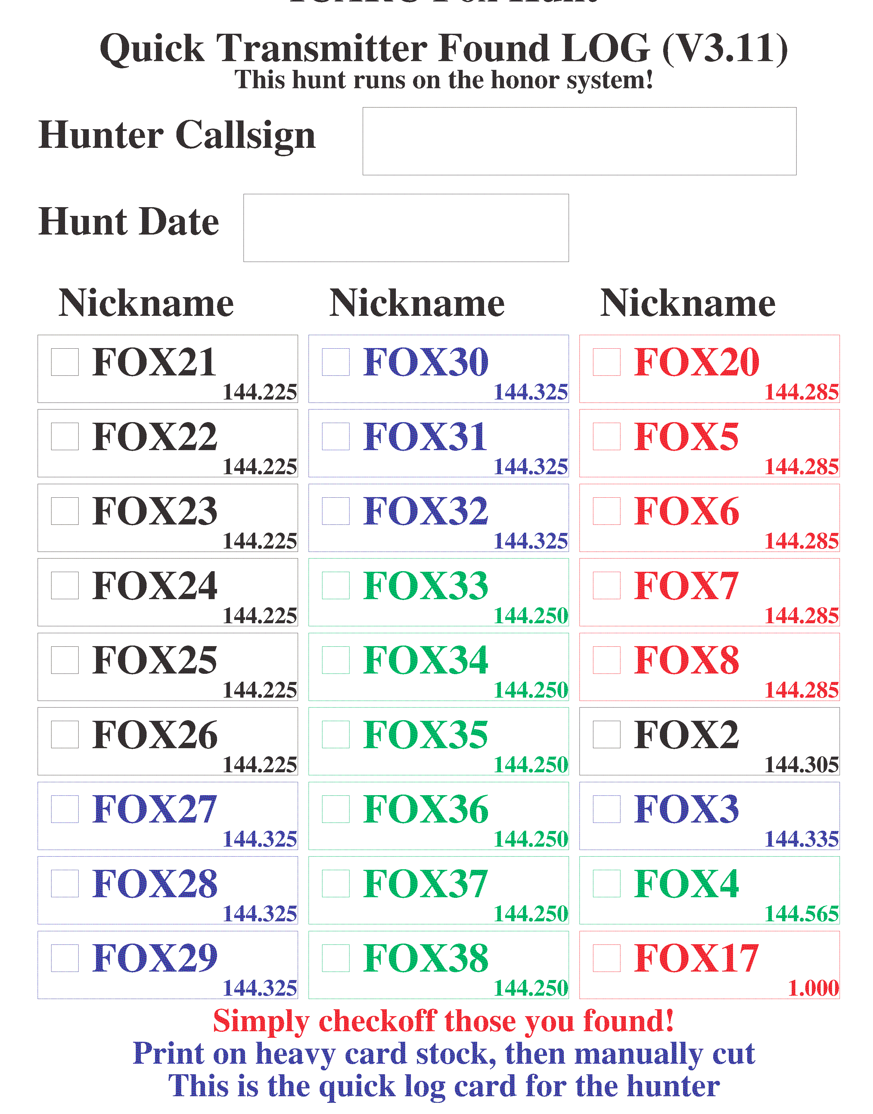
4.20 14 Oct 2025 0 KHz ext tab -1KHz ext tab -2KHz ext tab -3KHz ext tab -4KHz ext tab -5KHz ext tab -6KHz ext tab -7KHz ext tab -8KHz ext tab -9KHz ext tab -10KHz ext tab -11KHz ext tab -12KHz ext tab -9.2KHz for 25MHz Xtal 0KHz FM tab -1KHz FM tab -2KHz FM tab -3KHz FM tab -4KHz FM tab -5KHz FM tab -6KHz FM tab 0KHz 80M tab -300Hz 80M tab Audio Waveform Audio Waveform, extended Sample Config Expanded Config File Audio Directory Audio Directory, extended SX_CHIRP SX_STOOGE |
More GPS updates. Updates: Timeout handling for the GPS module seems to deal with missing GPS module correctly. module uartblk4_local updated to better handle traffic from the GPS module. module cmd_gps also updated to better handle traffic from the GPS module. Replaced all references to #include "uart_local.h" with #include "uartblk_local.h" Everyone has the same argument definition to match the current UART handler. Change the way timer_local.c decrements timer channels Behavior is now clear to zero when negative This triggered an update to the CW interrupt routine. Reduced the memory footprint of the cmd_conf module. Change the way the cmd_battery handles BATC IE command encoding to properly deal with current expressed in mA that exceeds 100mA. This revision supports HF operation and time synchronization using a GPS module. See the 102-73227-15 module for detail about operating in the 80M band and for details about connecting a GPS module ← HEX file to be loaded into FLASH (needs at least 4Mb FLASH) ← HEX file to be loaded into FLASH (many more clips from 3-Stooges, 2001 Space Oddesy, Star Trek) Needs at least 8Mb FLASH. ← ICARC Fox Hunt FRAM Prototype Configuration file (loads many transmitters!) ← ICARC Fox Hunt FRAM Expanded Configuration file (for the FOX21 transmitter!) ← ICARC Fox Hunt TALK Directory (same clips in all transmitters) ← ICARC Fox Hunt TALK Directory (for the extended audio load) ← ICARC Fox Hunt FRAM Prototype CHiRP sequence (simulates RADAR chirping) ← ICARC Fox Hunt FRAM Prototype 3-Stooges "You are now in Sing-Sing" (runs on 2 transmitters) |
|
4.19 |
Updates: TIME SAVE waits for RTI-0. More updates to GPST TIME command. Reworked GPS channel ISR to 2-buffer model The cmd_gps_decode.c code now validates the checksum in the NMEA sentence. The cmd_code.c module has CWPM command problem fixed We can use BEGN SILENT TXENA to enable the TX_ENA net in order to perform an uninterrupted frequency check In the cmd_code.c module, limit the code timing values to 31. The code_buffer field wheere these are stored is only 5 bits wide. The word rate is limited to 45WPM. In the cmd_stat.c module, display CW when we are in CW/AM mode! |
|
4.14 10 Aug 2025 |
Updates: Added TIME SAVE to update DS1672 from GPS module. Added time offset to GPST TIME command. Added TEST TIM to evaluate timing performance. |
|
4.12 04 Aug 2025 |
Updates: This update adds support for GPS modules for precise timing! 2 New RF boards to connect the GPS modules: 102-73227-15 and 102-73227-21. The 102-73227-15 board is for operation in the 80M band (official fox hunt band!). The 102-73227-21 board (Hi Power) is for operation in the 2M band. |
|
4.11 25 Jun 2025 |
Notes:
102-73161-12 and all 102-73181-xx boards! Updates: V4.11 updates Add EEPROM devices that look close enough to FRAM to be used on the older boards and provide for a large audio file system. V4.10 updates Eliminate frequency limits checking... Build the external table correctly! Eliminate all but ONE (144.100) internal entry [A We deal with ICS525 again here, but all entries are external! |
|
4.09 14 Jun 2025 |
Notes:
102-73161-12 and all 102-73181-xx boards! Updates: V4.09 updates Allows selecting frequency in 80M band (3.5MHz to 4MHz) Needs an external frequency table An alternate amplifier (102-73227-0) with LPF required! Sample table (zero offset) added ICS525 handler reworked to eliminate the internal frequency altogether. Requires an external frequency table! Note we are back to the broad hardware coverage (SI5351 and ICS525). V4.08 updates Fixed bad CALL and NAME substitution in the CODE command substitution is now correctly encoded... (Voice always worked right) |
|
4.07 (SI5351) |
Notes:
The SI5351 image only for 102-73181-10 This revision supports the (high speed) binary loader Updates: V4.07 updates Allows selecting frequency in FM broadcast band (88MHz to 108MHz) Needs external frequency table and changes to LPF! Broadcast FM is 15KHz so audio is very QUIET V4.06 updates Add the TIRP command to vebalize system seconds. Needs V_SEC and V_TIRP audio clips This allows checking the TOY clock through the RF channel. Removes some instructions from ISR to improve timing margins. ← Frequency Table for 25MHz crystal on SI5351 (9.2KHz offset for FOX33) ← FM Tables for operation in the 88-108MHz band. BAREFOOT ONLY! (no power amp allowed!) Hunt using a simple pocket radio... Audio is very quiet Good candidate for DTOA antenna switch. |
|
4.04 (SI5351) 24 Apr 2025 |
Notes:
The SI5351 image only for 102-73181-10 This revision supports the (high speed) binary loader Updates: V4.04 updates fix handling of CONF CW and CONF FM remove some debug code from UART ISR pull 2nd. char from UART in ISR (for 115,200) V4.03 updates fix problem processing ONCE V4.01 updates add binary mode for FRAM loading V4.00 updates add binary mode for FLASH loading These updates dramatically reduces FRAM/FLASH load times H56K PROG and H56K WAVE |
3.95 (SI5351) 01 Apr 2025 |
Notes:
The SI5351 image only for 102-73181-10 Updates: V3.95 updates add CONF XTAL xx.xx Document a non-standard SI5351 crystal selection V3.94 updates Add CONF FM same as CONF -AM or CONF -CW A little less confusion in the sequence files... |
|
3.93 (SI5351) 04 Mar 2025 |
Notes:
The SI5351 image is slightly smaller (102-73181-10 only!) The ICS525 image may be used on all hardware variants Updates: V3.93 updates Change the divisor for 115,200 b/s (closer to actual). V3.92 updates Change cmd_frequency.c to deal with 10M and 6M bands (SI5351). |
|
3.91 (SI5351) 3.91 (ICS525) 23 Feb 2025 |
Notes:
The SI5351 image is slightly smaller (102-73181-10 only!) The ICS525 image may be used on all hardware variants Updates: V3.91 updates BATR I dumps the battery coefficients table. V3.90 updates Add timetage to BATR command Battery report is self-contained (external timetag not needed). V3.89 updates Clean up some of the text reports. No functional change. |
|
3.88 08 Feb 2025 3.87 29 Jan 2025 |
Updates: V3.88 updates a line in the STAT command output. When the START command is used, a detail line is added to STAT. This line is tidy'd up a bit so it's easier to read. Alter CHRP command to deal with TALK files. The audio filename replaces the first argument. Other arguments remain, for the most part, unchanged. The short audio clip is scheduled the same as the audio tone. Fix issue with the REM- command. It was acting funny... Sometimes allowing commands to execute when they shoudn't. Add battery voltage limit test to BATV command. The battery vocalization will be followed by "SOS" in code if battery is below trip point. |
|
3.82 31 Dec 2024 |
Updates: Alter the way the the ERAS and ESAV commands deal with record erase. ERAS rewrites a record with MT** (changes from REM-). ESAV knows to replace the MT** record. The MT** record is visible with the EDMP command. Add the schedule name to the RUN0 status report. Debug aid; You will now see the activated schedule from the ANN= file. Add synchronous feature to WAIT command. This facility provide fine-grained synchronus scheduling. Allow inter-transmitter synchronization down at the seconds level.. Add a frequency parameter to the BEGN SILENT command Not intended for use in a sequence. RF debug aid for frequency and filter analysis. Change the SI5351 internal frequency table. The table now has the zero offset entries spread across the 2M band: 144.100 MHz 144.500 MHz 145.000 MHz 145.500 MHz 146.000 MHz 146.500 MHz 147.000 MHz 147.500 MHz This allows characterization of the crystal frequency error across the entire 2M band. |
|
3.76 19 Nov 2024 |
Updates: cmd_time V1.05 TIME command sets fox system to sub-second level (10mS) makes CHRP easier to overlap... You must send TIME twice! DS1672 doesn't like to wake up :-( You will need one of the external frequency tables to correctly set the SI5351. Measure the frequency error using the internal table: (FREQ 144.100) (BEGN) Measure (DONE) then load the appropriate external table into FRAM. You can generate more table entries at any time to extend operating frequencies. The audio waveform file is provided as an example. At a minimum, you will need to generate your own audio clips with with appropriate nicknames and callsign. The new audio data can be loaded after the provided file if you so desire. This will save generating number utterances, frequency utterances, and other "housekeeping" utterances. You may build your callsign and nicknames to load following the example table starting at address 0x40000, the existing vocalizations use up about 256KB of space in the FLASH, so you'll need at least a 4Mb device (512KB). A sample configuration file, as used by KC0JFQ (Sample Config). Keywords enclosed in apos (') cause a parameter substitution so this one configuration file can be used to load multiple fox transmitters. 'call' is more-or-less static (use one callsign for all stations) while 'name' and 'run' change for each station. |
|
3.75 03 Nov 2024 |
Updates: cmd_message V1.11 move to synchronous scheduling for CHRP... specify period and offset |
|
3.73 25 Jul 2024 |
Updates: cmd_help V1.02 clear uart_temp_buffer to ZERO before we start... command V3.21 add BATR command to allow collection of battery capacity data cmd_battery V1.07 add BATR command to report battery voltage and current add 5V rail to BATR command (early warning of end-of-life) batt_plot (external support utility) analyze BATR reports |
|
3.72 09 Jul 2024 |
Updates: add FOFF command to track offset in external frequency table. Internal SI5351 freq. table is very small and has 0Hz offset Si5351 requires external table for proper operation CONF command adjust reference xtal capacitor Default SI5351 crystal load is now 8pF. Change control port default speed to 56K. H56K name change to H115 HERA now support block mode STAR command working Add interrupted carrier control bit for "chirping" T2 default time increased to 150mS |
|
3.63 11 May 2024 |
Updates: Fixed bug in MODC command Added devices to FLASH/FRAM table Added check to allow console exit from HEX dump Add 32 bit address support for FLASH device larger than 128Mb Disable ALL SI5351 clocks (CLK0..CLK7) Fixed RUN0 command string matching |
|
3.54 23 Mar 2024 |
Updates: Audio sample rates 10K and 16K added Reworked how TEST and MAS jumpers are handled. 102-73161-25 voltage coefficient selection fixed. Recalculated battery sense coefficients. |
|
3.34 14 Mar 2024 |
Updates: Update for the 102-73181-10 boards. Compatible with 102-73161-25 and 102-73181-* DRA818/SA818 timing accommodations. SI5351 synthesizer. Expanded audio features (2nd. FLASH memory). |
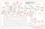
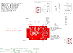
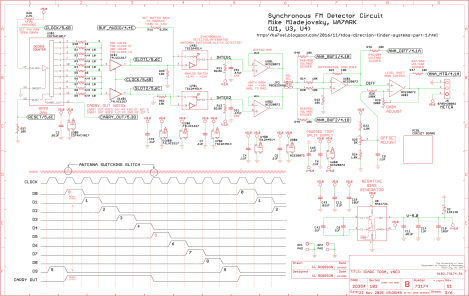
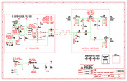 102_73170_A (TLC555)
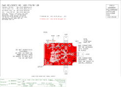
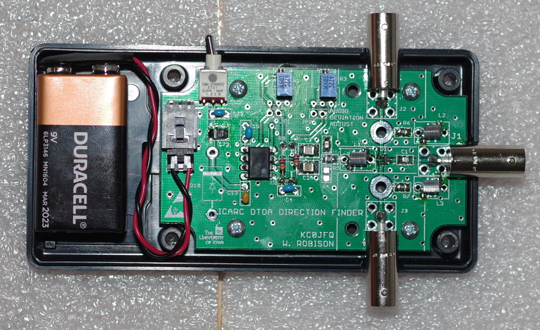
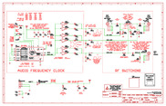 102_73170_20 (CD4047)
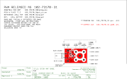
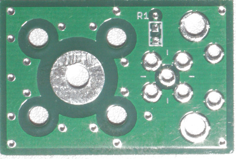
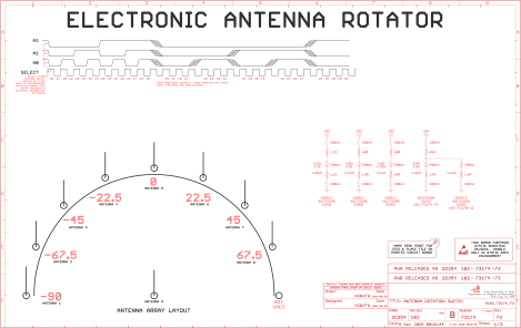
 102_73170_31 (ANT)
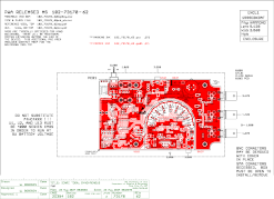
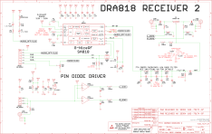
 102_73170_62 (CD4017)
 102_73170_A (TLC555)
 102_73170_20 (CD4047)
 102_73170_31 (ANT)
 102_73170_62 (CD4017)
 First prototype.
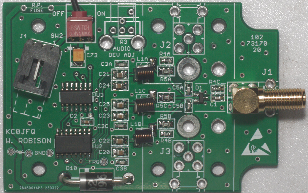 Second prototype.
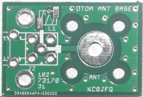
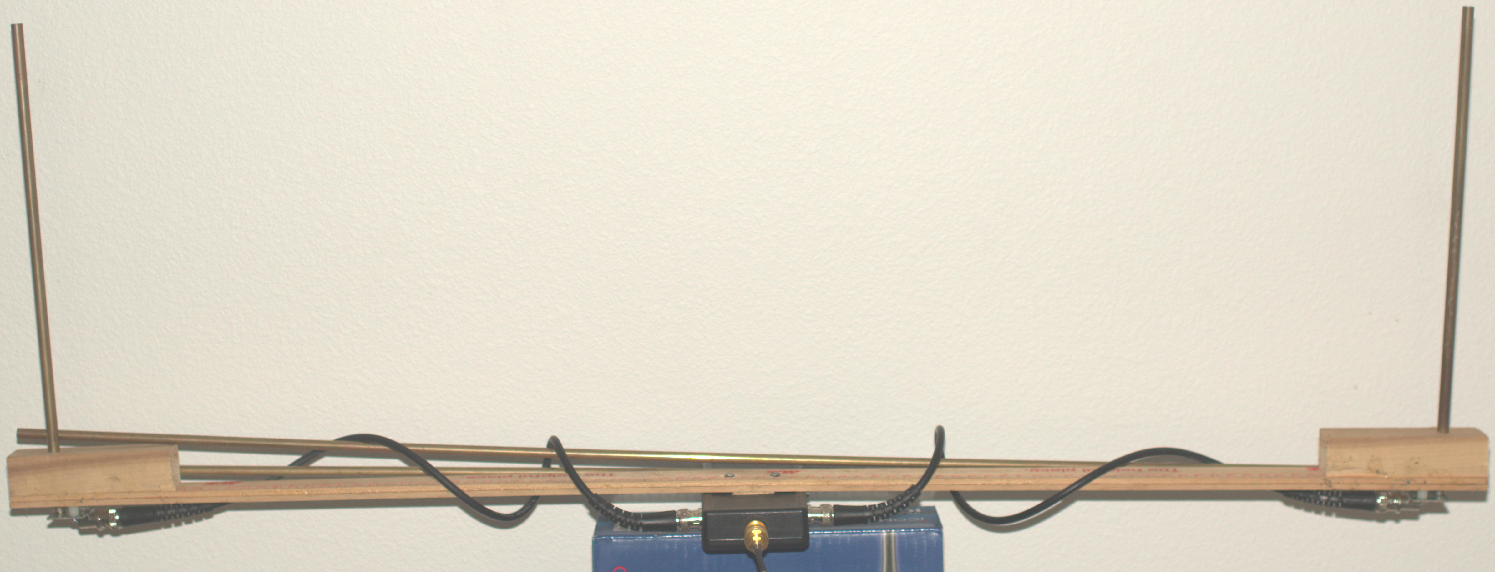
 Antenna Base.
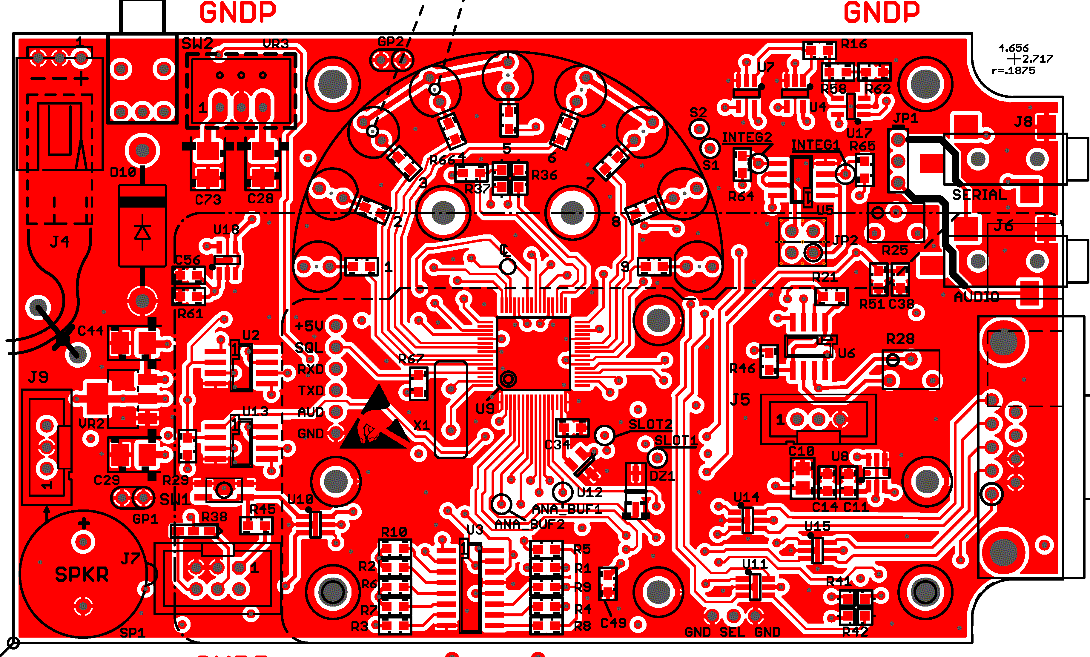 102-73174-51 Board
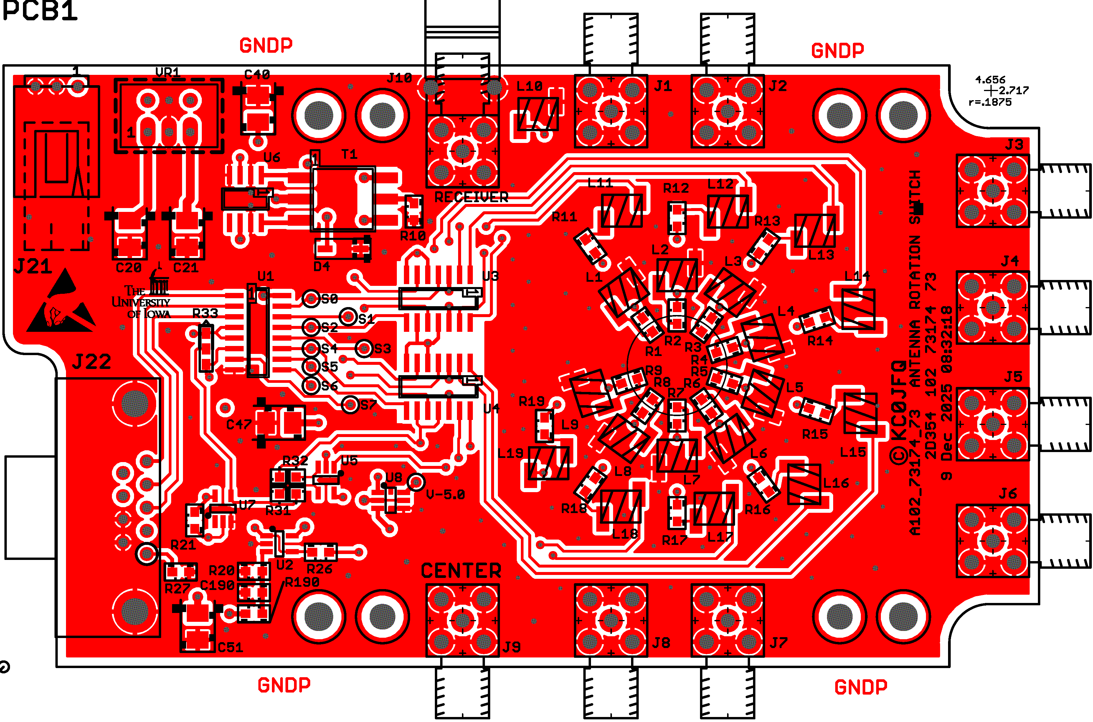 102-73174-73 Board
 102-73174-51 Schematics
 102-73174-73 Schematics
 102-73174-97 Board
 102-73174-97 Schematics
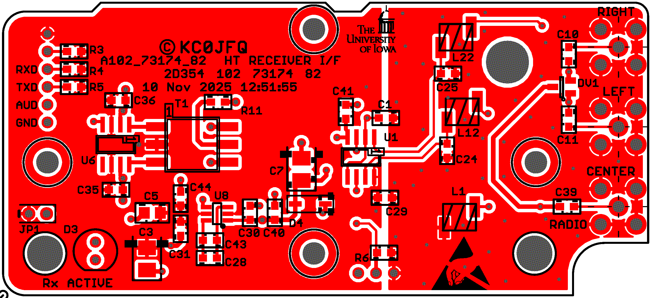 102-73174-82 Board
 102-73174-92 Schematics
Last verified 19 Jan 2021, email obfuscator incompatible!